|
So I gave a look at the certification for Revit Architecture, and on the Autodesk website I found plethora of information, tips and preparation material, including, a pre-test to take in order to see "where you stand", as they put it. The test is composed by forty seven questions, and it is pretty straightforward for whoever works in Revit professionally. However, I noticed some errors and inconsistencies which I thought were worth of mentioning, since this certification is not free, and I am worried about the quality of the final test. Lets look at some of the issues I found. 3D Views: Ortho vs. Perspective Answer #1 was marked as incorrect by the website. However, it appears to be the only one answer possible, even only considering the other three are obviously false: 3D view types have nothing to do with "overall building" versus "tight" spaces; nor with exterior versus interior; and certainly default 3D views are NOT static images. 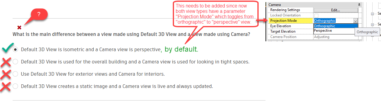 3D Extent at end of Levels / Grids This question is very confusing to me, see screen shot. 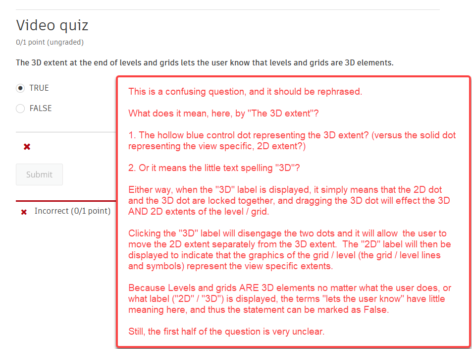 Color Fill Legends Here I may be splitting hairs, but I still think the answers could be more accurate. 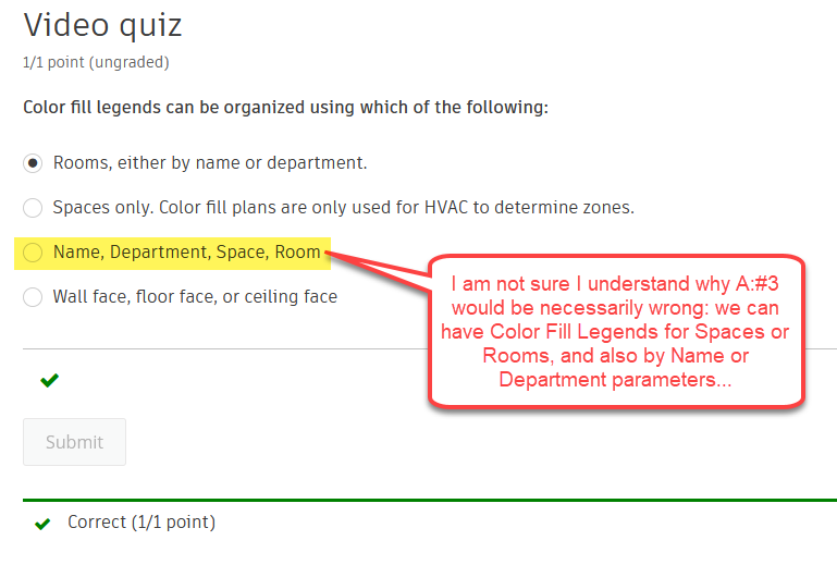 Automatic Embed Curtain Walls I think this one is quite straightforward, unless I am missing something. 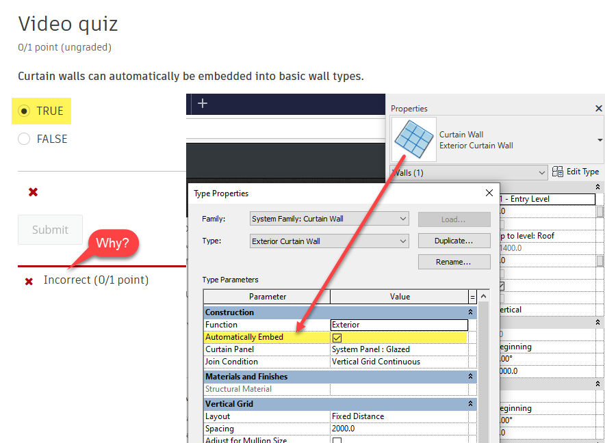 Detail Components Is this a matter of opinion? 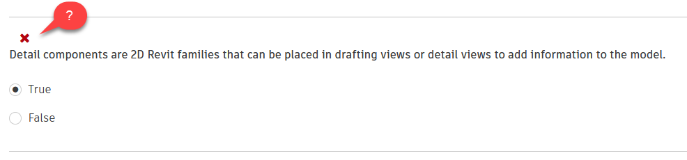 Duplicate with Dependent Here the pre-test question and the question at the end of the videos do not match. Also, the Video quiz has "Correct" written at the end of A:#4 (you had one job to do...) 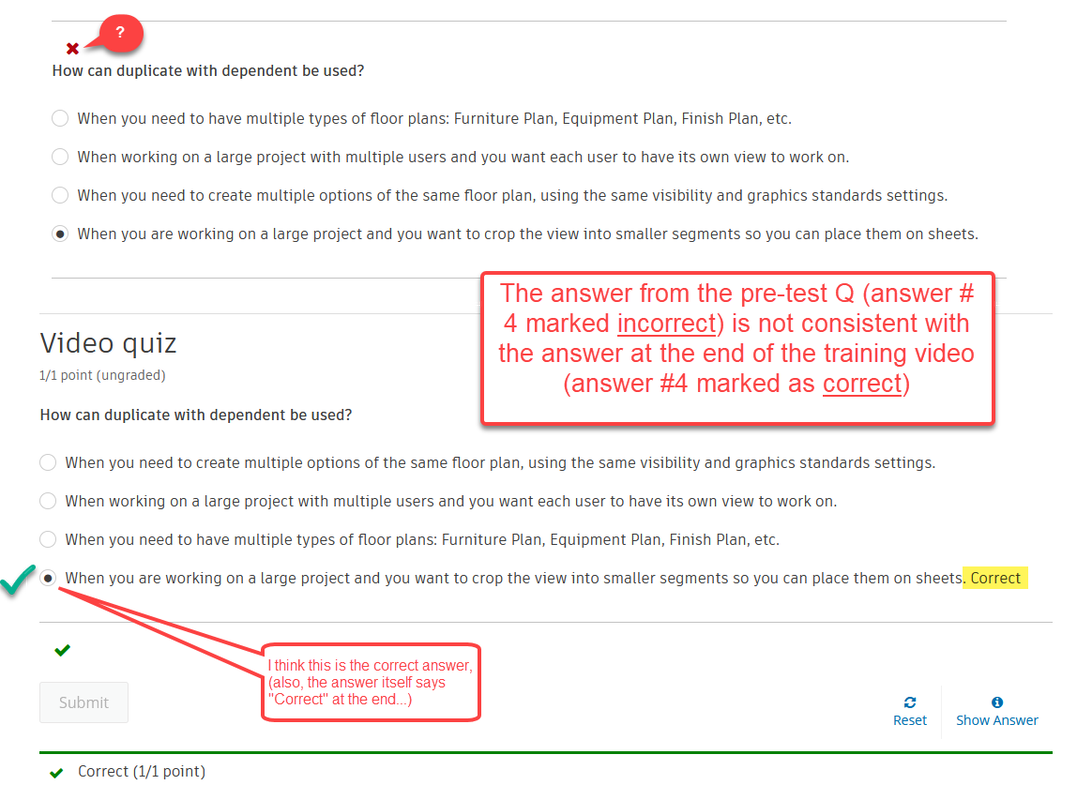 Duplicating with Detailing This next question needs more specific answers. 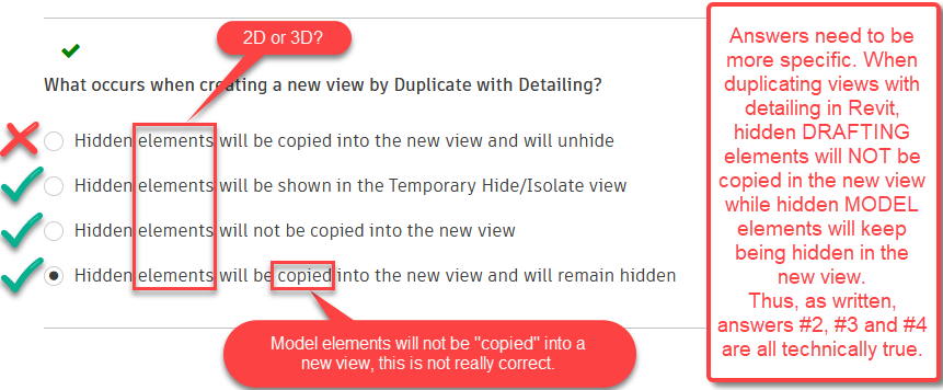 Use of Stacked Walls I am pretty sure this text was copied from another question, and the "NOT" was forgotten in... 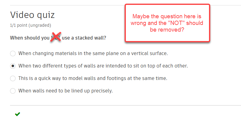 Openings By Face Even here there is an inconsistency between the pre-test question and the Video quiz: 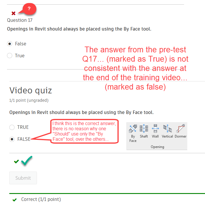 Rooms PlacementI believe Perkins&Will used this same question on their Revit assessments test, and they as well had it wrong... go figure. 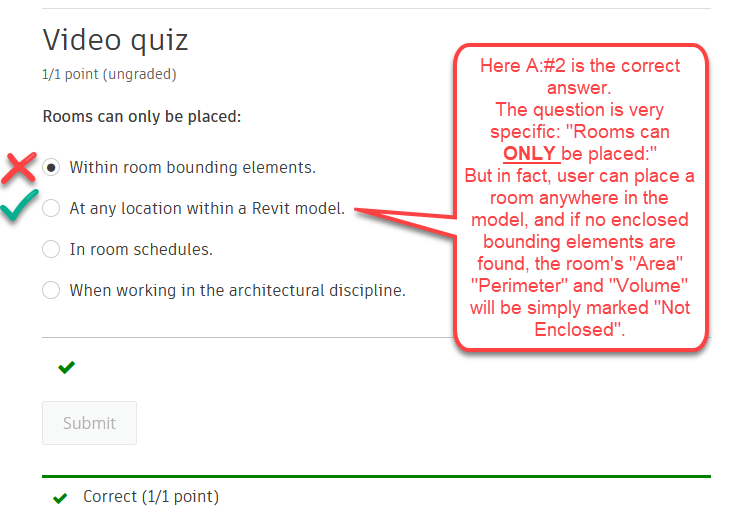 Shadows in Revit Here there are multiple answers true, but only one answer can be selected... 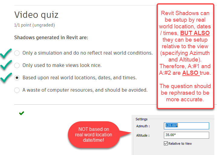 Stairs Top Level Association I think this statement is True, unless I am reading it in the wrong way. 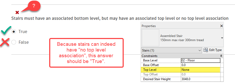 Subtractive Modeling Am I missing something? 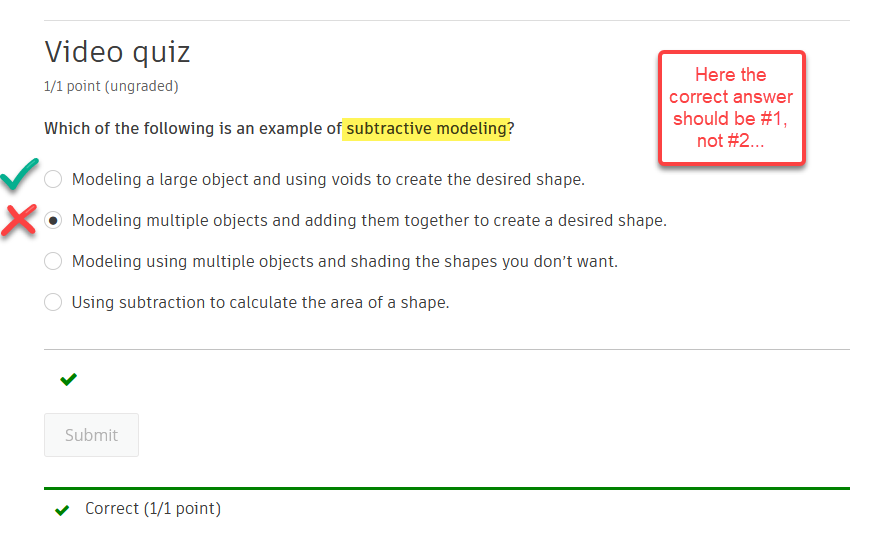
0 Comments
I noticed that a little feature has made its way into Revit 2014. I thought it was worth it a new blog post, since it is not discussed much around the Revit blog-sphere. Instead, I think it is a very powerful new feature. In Revit 2014, under the "Print Setup Settings" dialog box, within the "Options" box, at the bottom of the panel, you can see a new option switch, concerned with coincidental lines and "Region edges": see image below. This appears to be the much sough after ability to snap view edges to model lines WITHOUT the model lines line-weight being hidden or otherwise cropped by the view edges. In fact, the word choice is a bit unfortunate, since "Region edges" doesn't sound as View crop lines, but they actually are. In other words, not only this feature works with masking regions, but also with view crop lines. Or, if you want to be philosophical, maybe we can even say that in Revit 2014 view crop lines, being finally editable as a sketch, become much closer to actual masking regions. 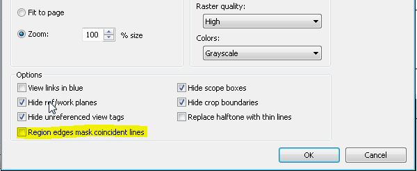 Anyone who has ever done interior elevations in Revit will immediately understand the importance of this feature: users do not need to manually nudge the view boundaries outward in order to display the line-weight of the model lines. Now, a Revit generated interior elevation will snap to the walls model line sections (as before) but the line-weight of those mode lines will print without reductions / cropping. Or maybe, not. Unfortunately, after some testing of this feature, I realized the cropping lines will not mask coincidental lines only if you first turn them into a sketch. In other words, in order to have clean interior elevation with minimal manual drafting, the process woul be:
 The View Crop lines should now leave the line-weight of coincidental lines intact, if you leave the new option unchecked, of course.
Despite being in version 2013, Revit still carries within it some quite unbelievably weak features (or lack of functional ones). Classic examples of these quirks with schedules are:
Once again, if you know of any work around, or if you have any philosophical take on these which to me appear to be inexplicable limitations of the software, by all means, please comment away. I have to work on a casework schedule to extract some information about cabinets and the rooms in which they are placed. If creating a new schedule and performing such task should be pretty straightforward, the team is now working on a half gig (yes GIG) model, and we have one hundred schedules in the browser. This dictates that before we create any new views, we should scavenge the (huge) model for already existing ones.
And here is the problem, because I did find a casework schedule (thanks also to the new search browser feature), but I do not know if it is placed on any sheet, or if it is a working schedule that can be modified without any existing sheet being modified. And no, "go check" is not a viable answer, because the browser also contains hundreds of sheets, grouped in dozen custom groups. So looking for the sheet where a particular schedule might have been placed is simply not feasible. Organizing the browser to filter out the "not on sheets" parameter works only on regular views, which is bad because Revit thought us that schedules are actually like any other graphic view of the data-set, that is, like floor plans or elevations, they are "sections" cut out of the same database of the 3D model. Yet, they are listed outside the "views" browser item and they seems to have less "rights" than other views. By the way, Legends seem to have similar limitations, in the sense that they cannot be screened out by "Not on sheet" and if you right click on a legend name, the menu item "Select all instances in view / entire project" is always grayed out. Why can't we at least know how many instances of a particular legend or schedule exist in the project is not clear at this point. This seems to be just an oversight. If anyone has any idea how to achieve this, please do post a reply. In the meanwhile, not to take any chance, I will have to create a new schedule. Many times 3D families have 2D elements drafted in them. For example, door families have the swing drafted in in plan view as a symbolic line (arc). Many other examples apply. However, there are some dangers in using nested 2D families within your 3D family: the nested 2D family must be a detail, and not an annotation! See the video below for an exhaustive example: Spot elevations work great to document the level of stairs landings, and other things like that. However, there is a little glitch in Revit that makes these tags not work in some cases. Specifically, spot elevation tags are not able to find a face to tag if the view is set to wire frame (and this is common knowledge), AND they do not work in plan views generated as DETAIL (and about this I could not find much on the web). In other words, a callout plan view will allow spot elevation to be placed, while a similar view created as a plan detail will NOT. I believe this is a Revit bug, since there is no reason why spot elevation tags should behave differently in different types of view. Here is an enlarged plan. Regrettably it was created as a DETAIL view: therefore the spot elevations are just detail lines with text: 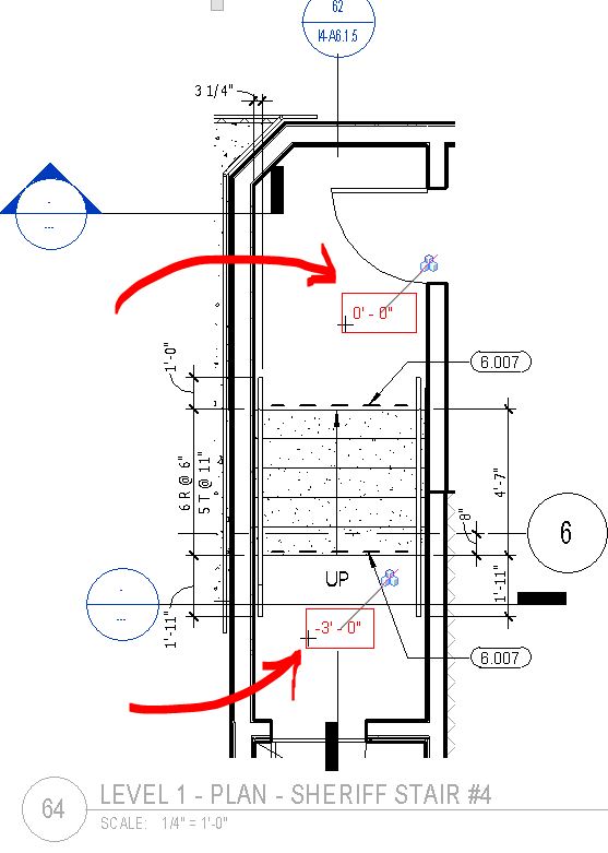 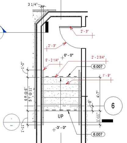 Interestingly enough, for some elements spot elevations DO WORK in detail views (see the red tags on the left). The tool finds doors' lines, railings, or stairs lines. I could not tag walls tough.
When you model a staircase you may believe that Revit will always respect the sacred belief that a BIM object will be "properly" represented in all type of views. For example, a 9 riser, 10 treads stair will show 9 risers and 10 treads in plan as much as in section (or elevation). However, I recently run into a weird Revit behavior that will make you (and any BIM purist) cringe in horror. All you need to do is create a monolithic stair with the Type Parameter "Begin with Riser" turned off. This means that the stair will actually begin with a tread. 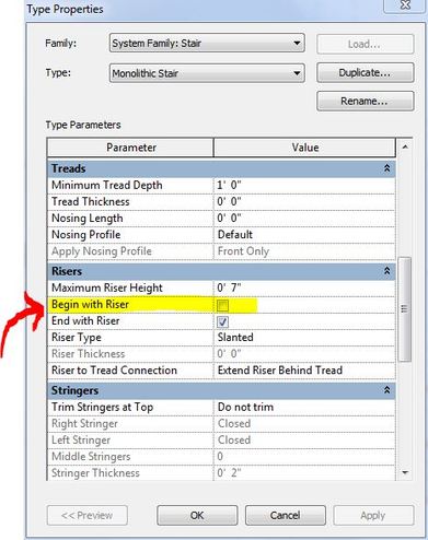 Now, for wood stairs and monolithic stairs with a tread thickness different from zero, this will still produce a model that is properly represented in plan and elevation/section. However, most monolithic stairs I have ever worked on do not have any tread thickness. In this specific case (very common) Revit will produce a representation of the stair in plan which is simply INCORRECT. In plan the stair appear to have 10 Risers and 9 Treads, however, the first riser shown in plan does not actually exist! 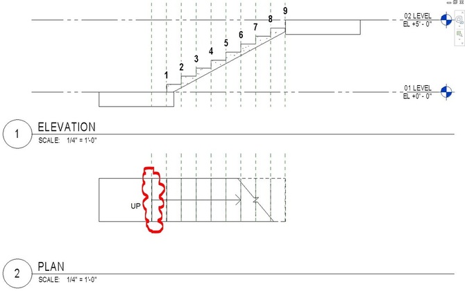 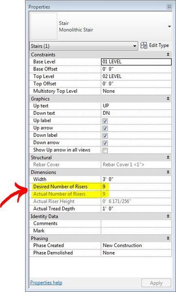 Looking at the instance properties of the stair, we can see that Revit properly shows that 9 Risers were created, but, again, in plan we count 10 Risers! If you set the thickness of the tread to some value (in this case I used 1 1/2"), then you can see that the stair actually does start with a tread, and this time the plan and elevation representations are congruous (or at least they make sense because it is easy to understand what that first line in plan represents). Of course, architecturally speaking, you should make clear that the first line in the staircase is not a riser but a change in material, or something along that line. 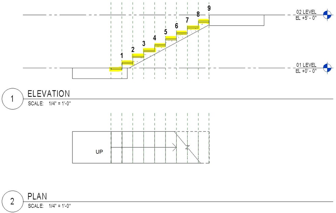 I just stumbled upon this European based site:
http://blog.revitforum.org/ Very interesting tips and tricks... Enjoy. Have you ever gotten the typical error "Can't create duplicates in edit group mode"? Then watch this video and I will show you how to keep working with no need to quit your group edit mode. Here is the Screencast version. |